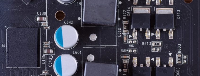
What is a Voltage Regulator and How Does it Work
A voltage regulator is a device that maintains the voltage of a power source within prescribed limits. This useful device keeps the output voltage at the same level even when loading conditions or input voltage changes. The voltage regulator comes in two types: linear and switching.
Linear Voltage and Switching Regulator Explained
A linear regulator uses an active pass device called bipolar junction transistor (BJT) or MOSFET) run by a high-gain differential amplifier. It basically differentiates the output voltage with a specific voltage then adjusts the pass device to keep the output voltage within the standard range.
On the other hand, a switching regulator works by converting the dc input voltage into different voltage using a switch. The dc output is then fed back to the circuit controller to regulate the transfer and keep the output voltage constant.
Switching Regulator Topologies
Topology is the study of geometric properties and spatial relations in Mathematics. Basically, topology is the way in which elements are arranged.
There are 3 main switching regulator topologies: buck (step-down), boost (step-up), and buck-boost which are a combination of both. The rest of the topologies are flyback, SEPIC, Cuk, push-pull, forward, full-bridge, and half-bridge.
In what way switching frequency impacts regulator designs
Switching frequency can affect the efficiency and performance of regulator designs. Higher switching frequency means greater noise, but this can be addressed by adding a low-pass filter.
However, adjusting the frequency depends on each system’s requirements. Also, higher switching frequency means reduced board space; the voltage regulator can use smaller capacitors and inductors.
What are Switching Losses?
Switching losses happen when the power switch changes from the ON state and OFF state and vice versa. Also, power or switching losses occur because there are more transitions per second when changing to higher frequencies. To sum it up, losses are associated with the activity of the power switch.
Linear Regulators vs. Switching Regulators
Linear regulator is the simplest technique to regulate the output voltage from the power source. It only requires a minimum amount of dropout voltage to work. Linear regulators are only suitable for low powered devices. It may be less complicated and cheap, but it is less efficient.
Switching regulators, on the other hand, are highly efficient and reliable. However, switching regulators emit loud squeal noise. Basically, switching regulators can drive higher current loads compared to linear regulators.
Switching Regulator Output Method Explained
The output voltage is controlled at a fixed limit by using three control methods: voltage mode control, current-mode control, and hysteresis (ripple) control.
What are the design specifications for voltage regulator IC?
Depending on the application, design specifications vary. But the primary specifications are input voltage, output voltage, and output current.
Other parameters that are important include output noise, load transient response, output ripple voltage, and efficiency. And for linear regulators, the important specifications are dropout voltage, output noise, and power supply rejection ratio or PSRR.
Additional Features for Voltage Regulator IC
Some regulators feature output voltage tracking which output voltage from one power source tracks the output of another power supply.
Linear MicroSystems, Inc. is proud to offer its services worldwide as well as the surrounding areas and cities around our Headquarters in Irvine, CA: Mission Viejo, Laguna Niguel, Huntington Beach, Santa Ana, Fountain Valley, Anaheim, Orange County, Fullerton, and Los Angeles.


